
DIY GPS Tracker With ESP32 - Python Application
![]()
In this project, we will make a DIY GPS Tracker With ESP32, we will use the MakePython ESP32 and A9G expansion board, it is a Python application.
I participated in a cycling event two weeks ago. After finished, I wanted to check the route and the speed I rode at that time. Unfortunately, it was not achieved. Now I use ESP32 to make a GPS tracker, and I will take it to record my cycling route next time. The GPS tracker can save the location and time information to the SD card, and this information can be processed and draw a chart of distance and speed with the PC software.
1. Materials for DIY GPS tracker
1.1 Hardware:
-
MakePython ESP32 (WROVER Version)
-
MakePython A9G, MakePython A9G expansion board is a GPS/GPRS dev board for MakePython.
-
Battery
-
Micro USB cable
1.2 Software:
-
Python 3
-
uPyCraft_v1.1
2. Hardware Connection
Connect two boards according to the pins, you will just need to plug in those 2 boards. The module can be powered by a battery or Micro USB cable.
3. Software Programming on PC
3.1 Python 3:
-
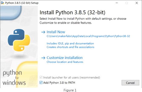
You can download it from here: Python3. Choose the 3.8.5 version, download and install it.
-
"Add Python 3.8 to PATH" selection must be checked during the installation process, as Figure 1.
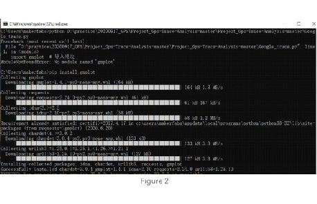
- If the library used by the program is not installed, the program will prompt when it is running. You can run the following command in cmd.exe to install libraries, as Figure 2.
pip install xxx   // xxx is library name
pip uninstall xxx   // xxx is library name
pip list    //   print installed libraries<br>
3.2 Code:
-
You can get the python file from here: Code. The python file is “/Project_Gps-Trace-Analysis-master/Google_trace.py”.
-
Draw a route on the map.
def create_html_map():
   gmap = gmplot.GoogleMapPlotter(lat_list[0], lon_list[0], 16)
   gmap.plot(lat_list, lon_list)
   gmap.marker(lat_list[0], lon_list[0], color='blue')
   gmap.marker(lat_list[width - 1], lon_list[width - 1], color='red')
   gmap.draw("./map-trace.html")<br>
-
Draw graphs of speed vs. time, distance vs. time.
 plt.subplot(2, 1, 1)
    plt.plot(time_list[0:-1], speed)
    plt.title("Average Speed:" + str(avg_speed))
    # plt.xlabel("Time")
    plt.ylabel("Speed(m/s)")
    plt.subplot(2, 1, 2)
    plt.plot(time_list[0:-1], total_distance)
    plt.title("Total Distance:" + str(round(total_distance[- 1],2)))
    plt.xlabel("Time")
    plt.ylabel("Distance(m)")
    plt.draw()
    plt.pause(0)
    pass
4. Firmware About ESP32
4.1 uPyCraft_v1.1
-
You can download it from here: uPyCraft.
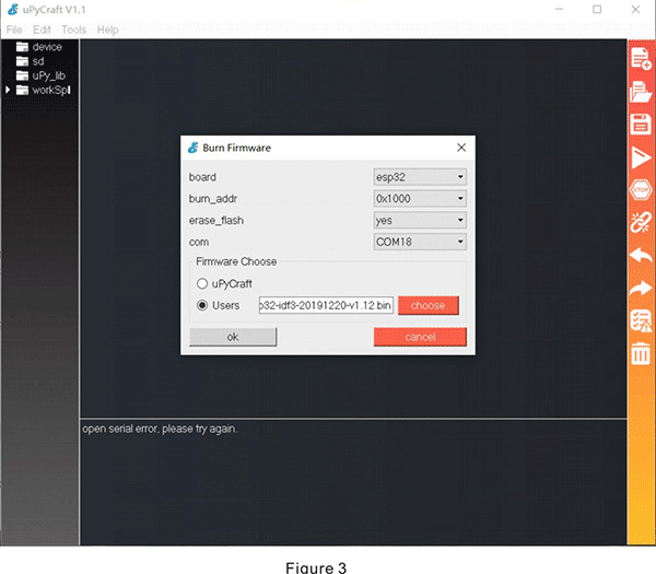
- Connect the board to the PC by USB cable. Open uPyCraft_v1.1, select the tools:” Tool > board > esp32” and “Tools > port > com*”, click the connected button on right.
- If the connection is not successful, the prompt will be shown as “open the serial error, please try again”. You have to update the firmware to promise connections successfully. The firmware download link is LINK. Open “Tools>BurnFirmware”, set the parameter, as Figure 3, and click OK.
-
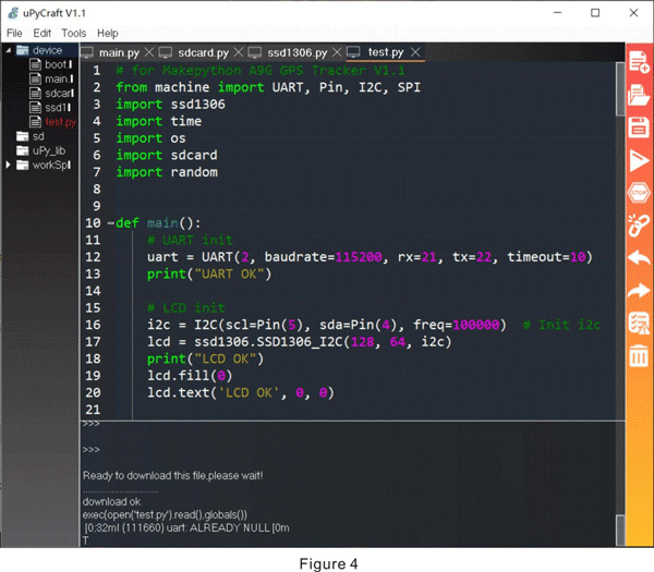
Open the Python file, and click the “DownloadAndRun” button on right. The program has been downloaded to the board, you can see it in the “device” menu on the left, as Figure 4.
4.2 Firmware and Download
You can get the firmware from here: Firmware.
-
Set the connection with SD card module in the file: “/Project_Gps-Trace-Analysis-master/workspace/test.py”
# SD init
    spi = SPI(1, baudrate=400000, polarity=1, phase=0, sck=Pin(14), mosi=Pin(13), miso=Pin(12))
    spi.init()  # Ensure right baudrate
    lcd.text('SPI OK', 0, 8)
    sd = sdcard.SDCard(spi, Pin(32))  # Compatible with PCB
    vfs = os.VfsFat(sd)
    os.mount(vfs, "/SD")
    random.seed(len(os.listdir("/SD")))
    print("SD OK")
    lcd.text('SPI OK', 0, 16)
-
Set the connection with the A9G module in the file: “/Project_Gps-Trace-Analysis-master/workspace/test.py”.
# A9G open
    A9G_RESET_PIN = Pin(33, Pin.OUT)
    A9G_RESET_PIN.value(0)  # set pin to low

    time.sleep(1)
    A9G_PWR_KEY = Pin(27, Pin.OUT)
    A9G_PWR_KEY.value(0)
    time.sleep(1)
    A9G_PWR_KEY.value(1)
    time.sleep(1)
    lcd.fill(0)
    lcd.text('A9G open', 0, 0)
-
AT command for the A9G module
AT+GPS=1   # 1: Turn the GPS on, 0: Turn the GPS off
AT+LOCATION=2   #Get the address information of GPS, as long as the GPS can see the satellite before returning, otherwise it will return GPS NOT FIX NOW
AT+GPSRD=0   #Stop reporting
Connect the board to the PC by USB cable, and use uPyCraft to download all files in folder “/Project_Gps-Trace-Analysis-master/workspace”.
5. Processing Information
-
Copy the TXT file beginning with "trace" in the SD card into the folder “/Project_Gps-Trace-Analysis-master”.
-
Open the Python file with the notepad and change the code.
#File which you want analysis
trace_file_name = "./trace4.txt"
-
Use the command line to run the Python file, you will get the figure of speed and distance, as Figure 5.
6. Let's try this ESP32 DIY GPS Tracker
If you have any further questions or need some PCBA customizations based on those MakePython IoT boards, feel free to contact service@makerfabs.com.