How to Make a DIY ESP32 Smart Clock at Home
This is a step-by-step guide about how to make a DIY ESP32 Smart Clock at home, it will need 1~2 hours of soldering and assembling.
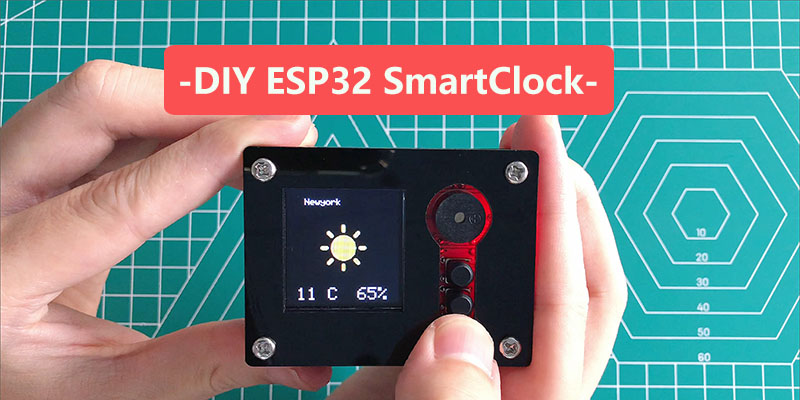
1. Introduce - What is this DIY ESP32 Smart Clock
This interesting kit provides all the parts to DIY an on-line clock& weather station in 1~2 hours’ learning of soldering& programming, could be a good first step to IOT projects for the electronic hardware learners& Kids.
The circuit board is based on ESP32, which support Arduino programming easily, all the necessary components, such as OLED display, buzzer, button are include in the kit, the users can solder them on the board manually, to enjoy the joy of DIY. Makerfabs provides firmware that can be upload to the board, to make the boards as a world clock, weather station. It is funny and exciting that DIY a smart clock of your own.
To reduce the difficulty of soldering, all SMD components are pre-soldered, it will take about 2 hours to solder this kit.
2. Features
● ESP32 WROOM module: WiFi, Bluetooth, 4MB Flash
● 1.44inch 128*128 color display, ST7735 driver
● Buzzer*1
● Button*3
● Micro USB interface
● Support Arduino
● 450mAh battery, support charge.
● Plug-in components, easy soldering.
● Need about 2 hours soldering
● 1.44inch 128*128 color display, ST7735 driver
● Buzzer*1
● Button*3
● Micro USB interface
● Support Arduino
● 450mAh battery, support charge.
● Plug-in components, easy soldering.
● Need about 2 hours soldering
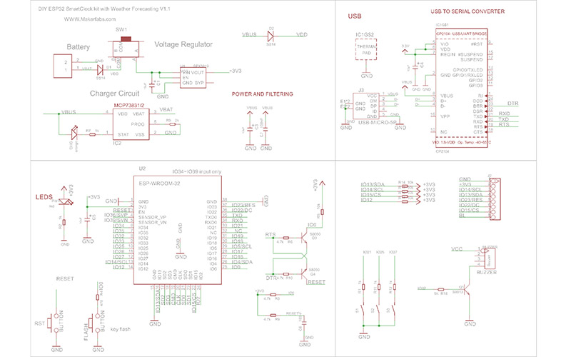
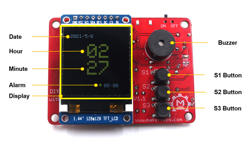
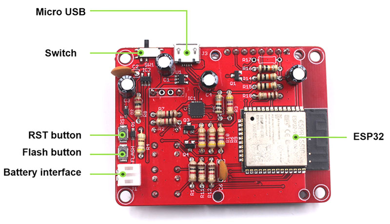
3. Diagram
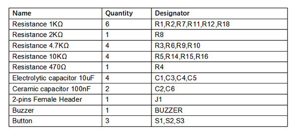
4. Part list
You can get all this components with this DIY ESP32 SmartClock Soldering Kit.
5. Soldering
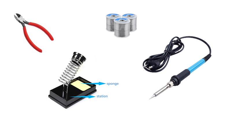
5.1 Soldering Tools
Below outline the tools and materials you will need for this project soldering:
● Solder
● Soldering iron
● Cleaning sponge
● Soldering iron stand
● Cutting plier
● Solder
● Soldering iron
● Cleaning sponge
● Soldering iron stand
● Cutting plier
5.2 Insert Electronic Component
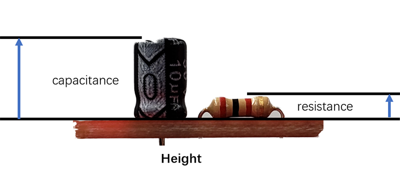
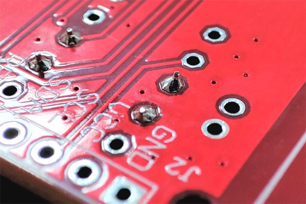
Start the soldering by inserting the electronic component into the pads of the circuit board, the order of the component to solder is determined by the high of the component. It is highly recommended to insert resistors in the pads and solder them firstly. When the lower height component (as resistor) been welded, they will not hinder the soldering of other components (such as capacitor). After the low components inserted, follow the below steps to solder them and cut out the extra lead..
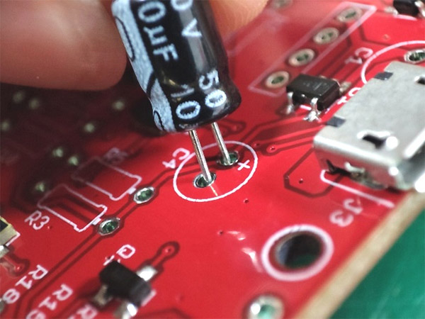
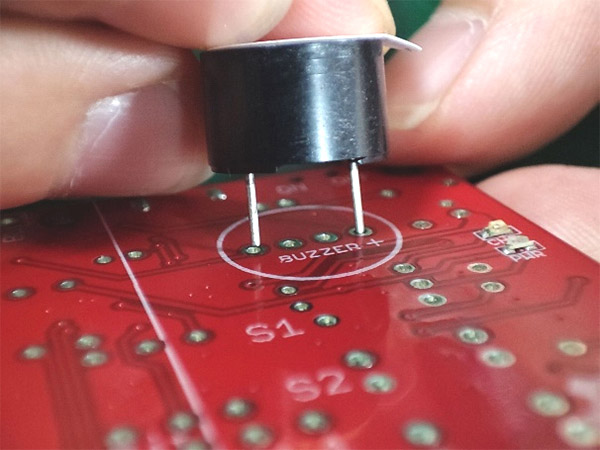
Note that the electrolytic capacitor and buzzer are polar. Refer to the polarity marking and on-board marking to insert the component, as the picture.


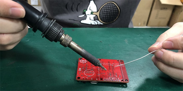
5.3 How to Solder
1. Safety first!
● Hold the soldering iron like a pen and near the basic of the soldering iron. Don’t touch the iron anywhere when the soldering is on or hot.
● Placed the soldering iron to the stand when the soldering iron is in idle.
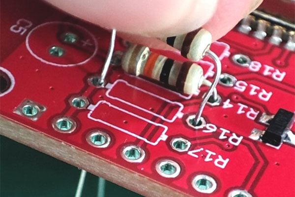
2. Below shows how to solder one lead of the electronic component (such the resistor):
● Begin by inserting the lead into the hole of the circuit board.
● Hold the soldering iron like a pen and near the basic of the soldering iron. Don’t touch the iron anywhere when the soldering is on or hot.
● Placed the soldering iron to the stand when the soldering iron is in idle.
2. Below shows how to solder one lead of the electronic component (such the resistor):
● Begin by inserting the lead into the hole of the circuit board.
● Turn on your soldering iron and let it heat up.
● Hold the soldering iron in one hand and solder in the other.
● Hold the soldering iron in one hand and solder in the other.
● Touch the tip of the soldering iron to the copper pad and the resistor lead. Hold the soldering iron in place for seconds to heat the connection. Both parts that are being soldered have to be hot to form a good connection.
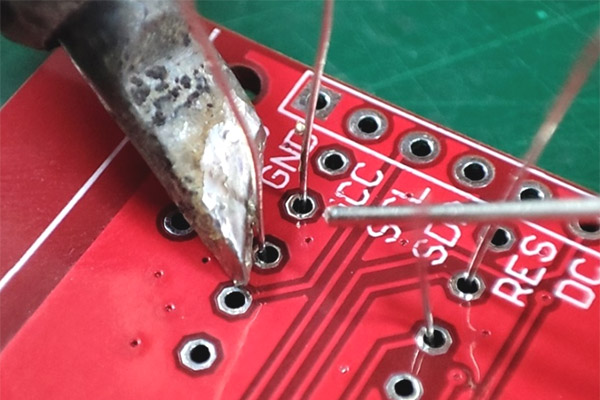
● Touch the solder to the joint, not the soldering iron directly.
● Remove the soldering iron and let the solder cool down naturally.
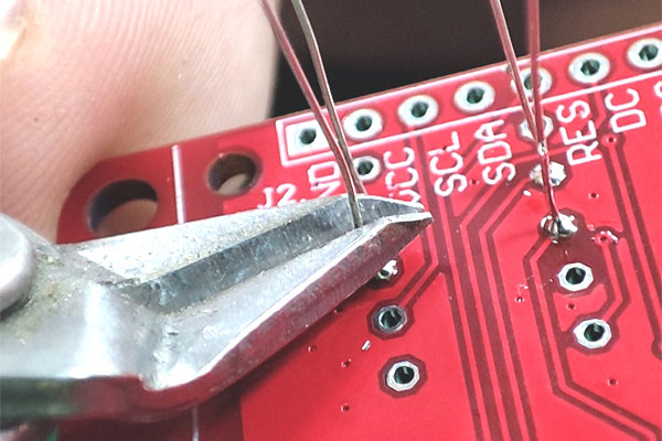
● Cut down the excess pinout.
● Cut down the excess pinout.
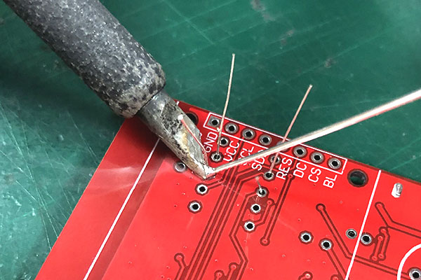
● A proper solder joint is smooth, shiny and looks like a volcano or cone shape.
3. If the iron tip is surrounded by oxide during the soldering, use the wet sponge to wipe it directly for clean which is helpful for soldering, though it will cause the tip cold.
4. It hard to avoid the bad connection between paths forming when soldering first time, don’t worry and it is easy to fix.
● If the place where the pad and lead meet wasn’t heating enough, it would form a bad connection. Place the solder iron to heat again and the solder will flow naturally to form a good connection.
● If the solder is not enough, place the soldering iron where the connection to heat, close the solder to add a little one.
● If the solder over-flow the welding pad, it may cause a short circuit when the solder touch other pad. It is necessary to remove the solder.
6. Usage
Power on the board (plug the USB cable or battery), press the button to on, the display will be light on. It means the board can work normally.
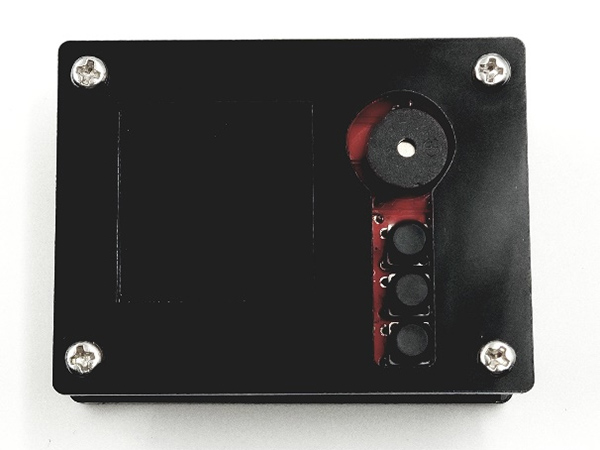
6.1 Assembly
There are acrylic shells and screws/ stands to package the PCBA and battery:


6.2 Clock Usage
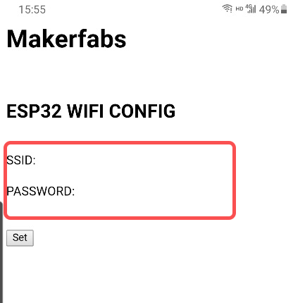
Set the ESP32 WiFi credential for connecting WiFi.
● When turning the power button on, press the button(S1) and hold it in 1S;
● When turning the power button on, press the button(S1) and hold it in 1S;
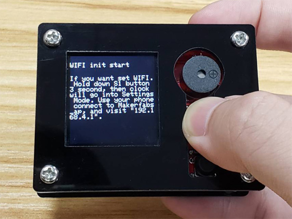
● Release the S1 button, use mobile phone or PC to connect the WiFi "Makerfabs_ap".

● Type the IP "192.168.4.1" to Chrome or other browsers on your phone to enter the server.
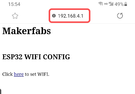
● Input your WiFi credential to the server, ESP32 will connect to WiFi after a minute.
● As WiFi connection setting finished, it will record the setting and connect the WiFi automatically. If the WiFi setting need to be updated, follow the above steps to retype WiFi credential again.
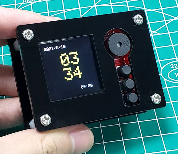
6.2.1 Clock
● After the WiFi setting or powering again, you will see the time shown on the display.
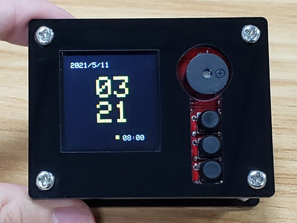
● The number in the bottom of right is the alarm time, and the point before the alarm time indicates that the alarm is activated. Press S3-button to disable the alarm.
6.2.2 Alarm Clock
● Press the S1-button to change the page to Alarm setting.
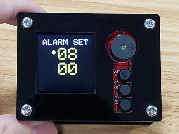
● Press S2-button to select the hour or minute.
● Press S3-button to add one to the value.
● When the alarm is ringing, press any button to pause it.
6.2.3 Time Zone
● Press the S1-button to change the page to Alarm setting.
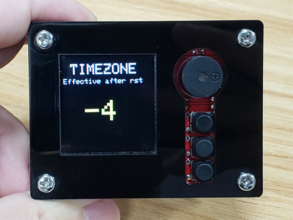
● Press the S3-button to modify the time zone to you want.
● When you finish the change, reset the board and the settings would take effect.
● When you finish the change, reset the board and the settings would take effect.
6.2.4 Weather
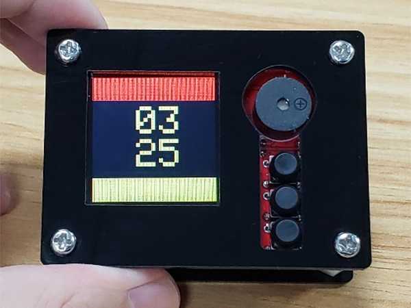
● Press the S1-button to change the clock page, the LCD will show the local weather, temperature and humidity.
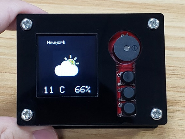
● You can press the S3-button to navigate the cities you pre-set in the firmware.
The DIY ESP32 Smart Clock is finish, enjoy!
The DIY ESP32 Smart Clock is finish, enjoy!