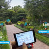
Transmit Temperature and Humidity to TTN with LoRawan
This project I will introduce you how to Transmit Temperature and Humidity to TTN with LoRaWAN, using the Maduino Zero LoraWAN Node.
In some of my previous projects, I was using some LoRa modules to achieve certain effects. Some people who interested asked whether the project support the LoRaWAN or the module can transmit the data to TTN (the things network) by LoRaWAN. Unfortunately, my answer is NO.
So I wanted to build a project to transmit the data measured with the DHT11 module to TTN by LoRaWAN.
1. LoRaWAN Board
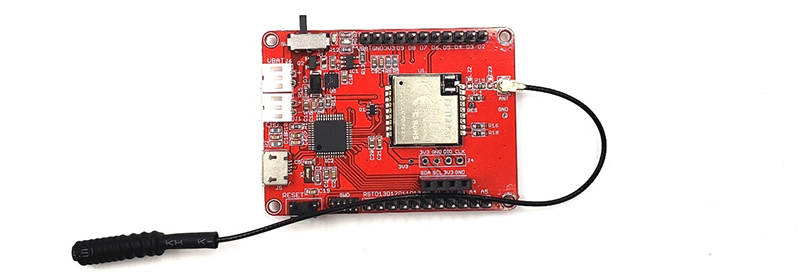
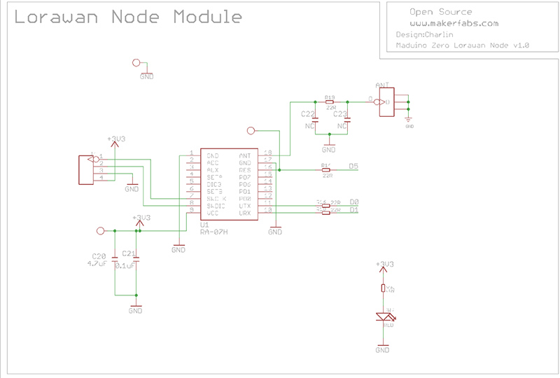
I used the LoRaWAN Board designed by Makerfabs that base on SAMD21G18A microcontroller and RA-07H LoRaWAN module that is compatible for Arduino I good at. The LoRaWAN board provides many expansion GPIO for connecting the sensor, and they met my need for connecting the DHT11 module.
Ra-07H module already have firmware that support the AT command. According to the LoRaWAN board schematic, the Ra-07h connects with MCU through the serial that you can send the AT command to LoRaWAN module by serial.
After I got the board, I did the tests for it: does the module can be used to communicate with the LoRa module. In fact, these are two different module and did not talk to each other. Next, I was going to start transmit the data by using LoRaWAN board.
2. How to Set an Application on TTN
Frist, it is necessary to learn how to use the TTN and set the application. There are three parameters to pay more attention: device EUI, APP EUI, APP KEY. These parameters are the key for LoRaWAN module to transmit the data to Application of TTN.1. Enter the TTN website: https://console.thethingsnetwork.org/, and log in the account.
2. Go to the console, select a cluster to start adding devices. (I choose the EU)
3. Select Application in the page, and add a new application.
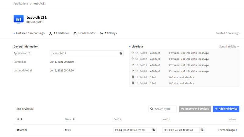
4. Fill the application ID and other information, then create it.
5. Add an end device, select the manually to fill the Active mode as OTAA and LoRaWAN version, then follow the prompts to type the parameters that will set.
6. In the Device of the Application, three parameters will be seen that I had to put these to the code.
7. In the device page, it is necessary to set the payload formatters for decode the payload LoRaWAN node transmitted. Choose the Uplink and select the Javascript. Type in the follow code and save.
 function Decoder(b, port) {
  var var1 = b[0];
  var var2 = (b[1] << 8) | b[2];

  return {
    field1: var1,
    field2: var2/10
  }
}
3. How to transmit data to TTN
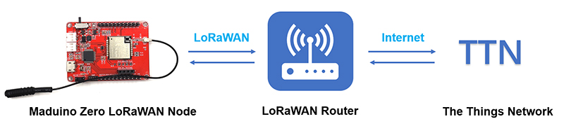
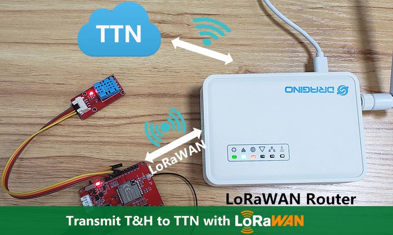
Focus on the LoRaWAN Board, it does not connect the TTN directly as the node. As the picture shown, LoRaWAN module transmit the data to LoRaWAN router by LoRaWAN, then the router transmits the data to TTN through internet. So that the LoRaWAN cannot send the data to TTN without Router.
The LoRaWAN Router I used is the Dragino one, that it have to be loaded the firmware and configed to be a TTN gateway.
Next will show the mode LoRaWAN module work in and the AT commands used. There are two working modes that the LoRaWAN module join to the LoRaWAN: OTAA (Over The Air Activation) and ABP (Activation By Personalization). OTAA join mode is recommend to use for confidentiality. In the OTAA join mode, LoRaWAN module have to configure three parameters Mentioned above. It does no need to set the LoRa frequency that it will connect the Router one automatically.
4. Coding
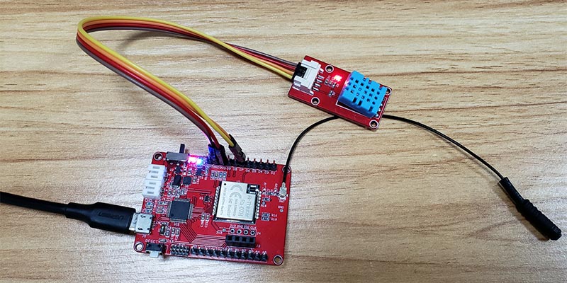
Connected the DHT11 module to the LoRaWAN board, loaded the firmware to the board by Arduino that the firmware is available on the Github. Note to modify the parameters to yours.
Then the measurement data would be transmitted to the TTN.
AT commands used:
AT+CDEVEUI=**********           set the device EUI parameter
AT+CAPPEUI=**********           set the APP EUI parameter
AT+CAPPKEY=********** set the APP KEY parameter
AT+CJOINMODE=0 set the join mode to OTAA
AT+CJOIN=1,0,10,1 config the OTAA mode, first “1” enable the OTAA, “0” turn off the automatic of joining, “10” is the cycle time of joining. Second “1” is mean only one time to join.
AT+DTRX=1,2,5,******* “5” is the string length, “*******” is the payload.
5. Result
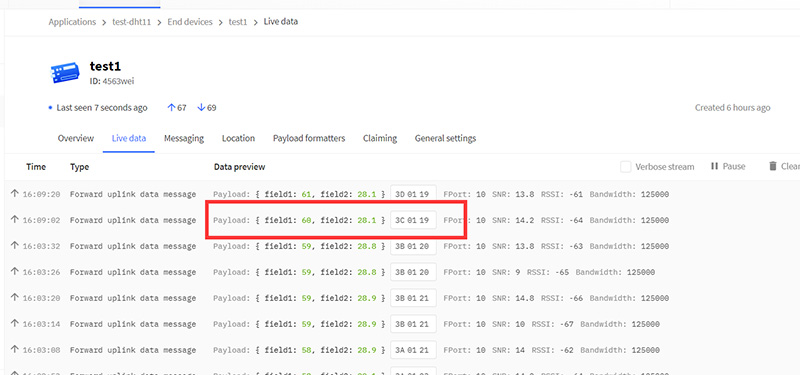
As the picture, the original payload is 3C0119, the date after payload formatter decoded are 60 and 28.1, it mean that the temperature is 28.1 °C and humidity is 60%.
If you have further questions for this tutorial about Display Image with Raspberry Pi Pico by Arduino Programming, or need Turnkey PCBA service, pls contact service@makerfabs.com.