
How to Make an Ultrasonic Levitation Device
This article will introduce how to make an ultrasonic levitation device, allowing you to experience the scenes in sci-fi blockbusters at home.
Technologies such as suspended particle manipulation and aerial imaging in "Star Wars" and "Star Trek" have been realized in reality. This article will introduce a set of acoustic suspension devices, allowing you to experience the scenes in sci-fi blockbusters at home.
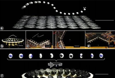
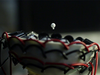
A picture of unilateral levitation in mid-air. Expanded polystyrene particles about 1 mm in diameter are suspended on a single-sided array. (a-c) Particles can translate along three-dimensional paths up to 25 cm.
Do you want to try it yourself when you see such a magical operation? Let's walk into the making of the ultrasonic levitation device.
1. Scientific Background
Sound can suspend objects of different sizes and materials through air, water, and tissue. Acoustic sensors can generate ultrasonic phased arrays after specific arrangements and combinations. Single-sided emitters can be used to translate, rotate, and manipulate particles. Holographic acoustics are also introduced. Elemental framework that allows rapid trap generation and bridges the gap between optical and acoustic trapping. When the trap is strong enough to support the tiny spheres and counteract gravity in any direction.
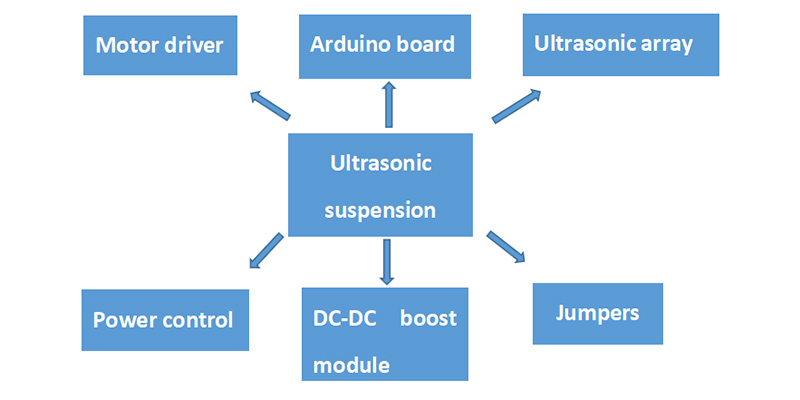
2. Composition of Mechanical Modules
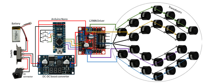
The tractor beam equipment in this paper is mainly composed of the following modules, the details are shown in Figure 1 below, and the physical connection diagram is shown in Figure 2 below.The power control module consists of 1 × 2s lithium battery (7.3V) and a 6-pin switch, the battery (7.3V) powers the logic part of the Arduino and the motor driver.
The Arduino control board adopts Arduino Nano, which is a development board based on ATmega328P. Can be plugged directly into the breadboard. The Arduino Nano has no DC voltage power supply interface and the Nano is connected to the computer through the Mini-B USB interface.
The ultrasonic array module includes 24 ultrasonic sensors and 1 3D printing bowl. The ultrasonic sensor adopts the 16mm 40kHz sensor of the model MSO-P2A1640AH12TR, and other alternatives are also available. The 3D printed bowl uses an Ultimaker Extended 2+ with a 0.4mm nozzle and normal settings. There is no support, only the brim.
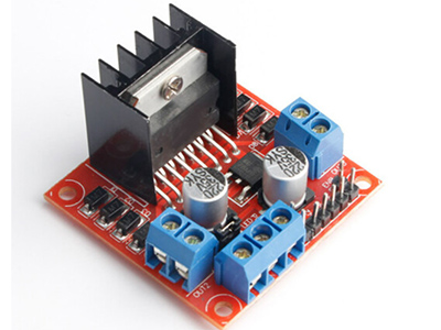
The motor drive module L298N is a high-voltage and high-current full-bridge driver with two H-bridges, which can be used to drive inductive loads such as DC motors, stepper motors, and relay coils.
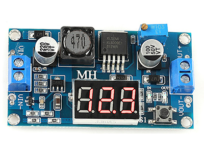
The boost module is the XL6009DC-DC boost converter, which can boost the motor driver's 7.3V to 25V.
In addition, 12AWG black and red wires, 29 SWG bare wires, and some jumpers are required for circuit connection.
3. Principle of Ultrasonic Suspension
The ultrasonic suspension device generates a 40KHz square wave signal through the output port of Arduino nano, amplifies the 40KHz square wave signal generated by Arduino nano under the drive of the motor, and drives the motor drive module with the amplified 25V voltage to transmit ultrasonic waves The device produces a strong interaction force that overcomes its own gravity. Based on the above principles we will make a mysterious tractor beam that can attract particles to the source.
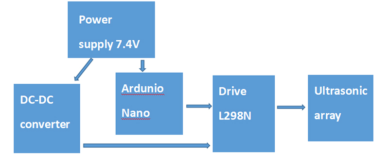
4. Circuit Connection
The circuit logic is as follows. The power supply supplies power to the DC converter and the Arduino at the same time. The Arduino outputs a square wave signal through the A0-A3 ports. The DC module converts the 7.4V voltage to 25V and supplies it to the L298N. and feed into the sensor. The button pad can be used to change the phase so that the particles move up and down.
Notice:
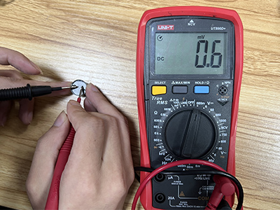
The ultrasonic array needs to be installed in the 3D printing bowl, that is, the rotating drum. The effect diagram is as shown in Figure 5. This shape allows the beam to be focused naturally. Special attention is that the positive electrode of the ultrasonic wave is upward and the negative electrode is downward during installation. The operation of testing the positive and negative electrodes of the ultrasonic wave is as follows, adjust the multimeter to the DC voltage level (mv), the positive and negative electrodes are respectively connected to the two pins A and B of the ultrasonic sensor MSO-P2A1640AH12TR, if the multimeter shows a positive voltage, mark the A pin, otherwise mark the B pin, as shown in the photos:
1. Measure both pin voltages
2. Mark the positive pin for positive voltage
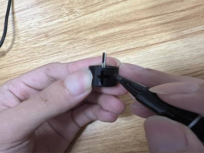
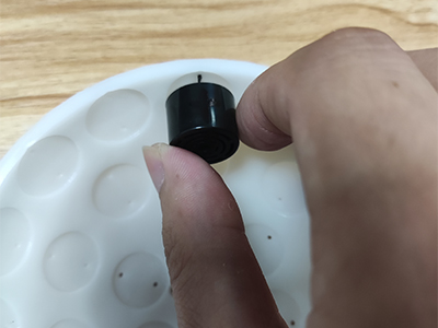
3. Mark the pins up
4. Complete the installation 14+10
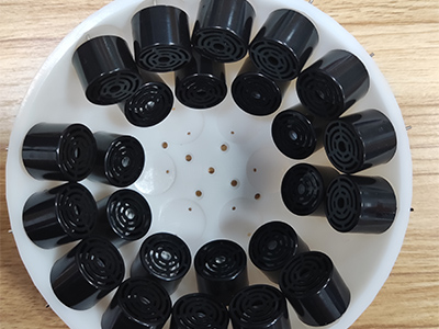
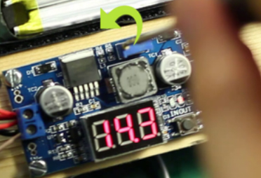
The voltage converter needs to manually adjust the voltage to 25V for the successful realization of the suspension device after access to the drive. The picture after the correct installation is as follows.
Is it easy to disassemble each module? Let's move on.


Notice:
The ultrasonic array needs to be installed in the 3D printing bowl, that is, the rotating drum. The effect diagram is as shown in Figure 5. This shape allows the beam to be focused naturally. Special attention is that the positive electrode of the ultrasonic wave is upward and the negative electrode is downward during installation. The operation of testing the positive and negative electrodes of the ultrasonic wave is as follows, adjust the multimeter to the DC voltage level (mv), the positive and negative electrodes are respectively connected to the two pins A and B of the ultrasonic sensor MSO-P2A1640AH12TR, if the multimeter shows a positive voltage, mark the A pin, otherwise mark the B pin, as shown in the photos:
1. Measure both pin voltages
2. Mark the positive pin for positive voltage
3. Mark the pins up
4. Complete the installation 14+10


The voltage converter needs to manually adjust the voltage to 25V for the successful realization of the suspension device after access to the drive. The picture after the correct installation is as follows.

Is it easy to disassemble each module? Let's move on.
5. Circuit Principle
What needs to be explained in this setting is the working principle of the boost converter. The main working mode of the DC conversion circuit is the pulse width modulation (PWM) working mode. The duty cycle (ratio of pulse width to pulse period) of the square wave to change the voltage.
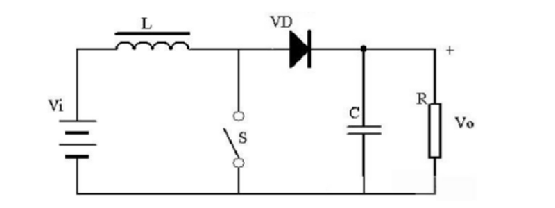
Figure 5
The schematic diagram of the boost converter is shown in Figure 5. When the switch is closed, the input voltage is applied to the inductor. At this time, the inductor is excited by the voltage (Vi), and the magnetic flux added by the inductor is: (Vi)*Ton.
When the switch is turned off, due to the continuous output current, the diode VD becomes conductive, the inductance is clipped, and the magnetic flux reduced by the inductance is: (Vo-Vi)*Toff.
When the switch-on and switch-off states reach a balance, (Vi)*Ton=(Vo-Vi)*Toff, since the duty cycle D<1, Vi<Vo, the boost function is realized.
6. Software Part
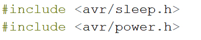
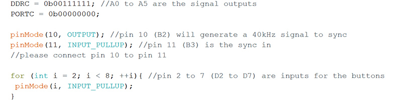
The development software uses Arduino IDE, no need to download third-party libraries, and uses Arduino's own library files avr/sleep and avr/power to define the square wave generation function.

A square wave of 40KHZ is generated through pin 10, and an ultrasonic phased array is formed through an ultrasonic array.
Import the program into the hardware circuit, and a simple ultrasonic suspension device can be completed.
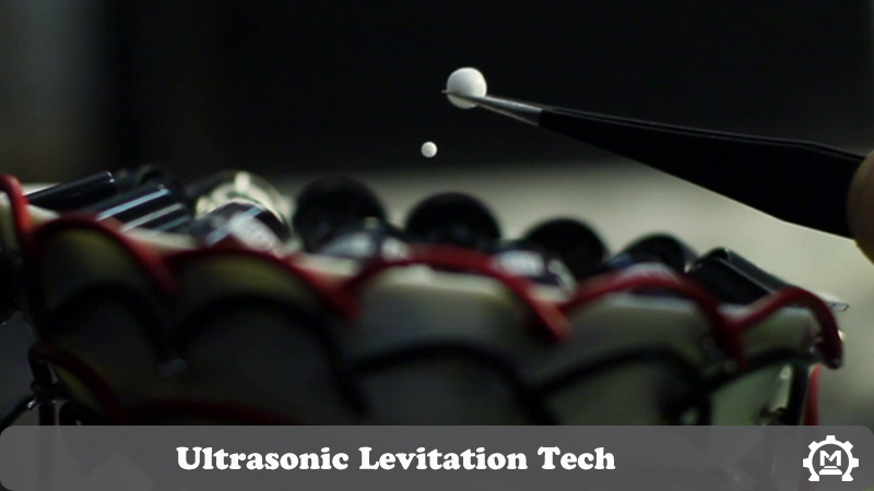
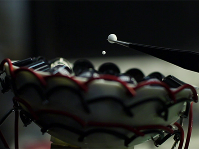
Using tweezers, you can place the pellets about 2cm in the center of the bowl and they will be suspended. Press the button to move the particle up or down.
Depending on the size of the particle and its distance from the bowl, you will be able to suspend it sideways or upside down.
This sharing is here, let's start making it. You can get the kit by: Acoustic Levitator. If you have any problem or need custom PCB assembly service please contact service@makerfabs.com.


A square wave of 40KHZ is generated through pin 10, and an ultrasonic phased array is formed through an ultrasonic array.

Import the program into the hardware circuit, and a simple ultrasonic suspension device can be completed.
Using tweezers, you can place the pellets about 2cm in the center of the bowl and they will be suspended. Press the button to move the particle up or down.
Depending on the size of the particle and its distance from the bowl, you will be able to suspend it sideways or upside down.


This sharing is here, let's start making it. You can get the kit by: Acoustic Levitator. If you have any problem or need custom PCB assembly service please contact service@makerfabs.com.
Related Blogs
- [2023-06-26] Exclusive Giveaway Event - Win Exciting Prizes: $200 Coupon or Raspberry Pi 4 Computer 8GB!
- [2022-12-07] Cautions in Using ESP32 ADC - Makerfabs
- [2022-09-06] ESP8266 WiFi Shield Firmware Upgrade V1.0
- [2022-07-15] Production Errors of Lora Soil Moisture Sensors
- [2022-01-14] 2022 Spring Festival Holiday Notice