PCB Assembly(PCBA): 4 Steps and Related Machines Needed
PCB Assembly(PCBA): 4 Steps and Related Machines Needed
For PCBA prototyping, manually soldering is a good choice, depends on your experience and soldering skill, it is cost-effective, and also saves time from communication/shipping back and forth. But when it comes to 20 pcs, or even 50 pcs, manual soldering is not a good choice, that professional assembly with machines is needed.
How all the tiny components are stuck on the PCB boards with machines? Sometimes this could be a problem for makers, hobbyists, even engineers. But actually, there is nothing magical about PCBA manufacturing, and sometimes even boring, about the soldering. Know more about the PCB assembly could be helpful for engineers to design the boards, and enhance the production pass-rate.
So, let’s dip into the PCB assembly procedure. In this blog, we will introduce some of the machines, and related materials/tools needed in printed circuit boards assembly; in further blogs, I will explain how these machines works, and the related specs, and what should be taken into consideration in the PCB boards design, to enhance the production pass rate.
Firstly, In PCB assembly, you will always see the words "SMT Assembly", SMT is Surface Mounted Technology, it means soldering all the surface mount components on the PCB, there are 4 main stages:
- Solder Pasting
- Automated Component Placement
- Wave Soldering
- Inspection
1: Solder Pasting Stage
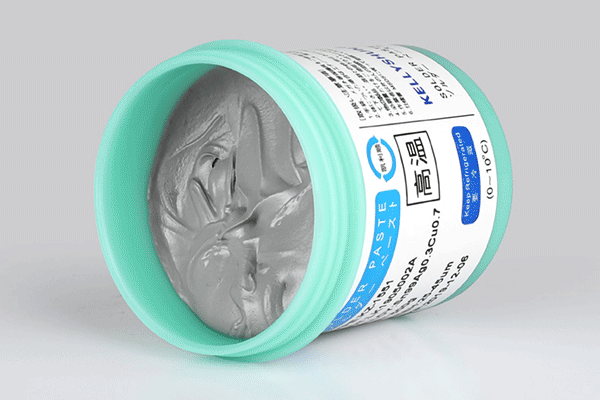
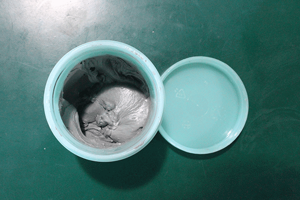
1.1 Solder Paste
Solder paste (or solder cream) is the key material for soldering. As Wikipedia, it is “a material used in the manufacture of printed circuit boards to connect surface mount components to pads on the board”. The paste is sticky initially, it adheres components on the PCB board if heated(need to be strict as the temperature curve), it will melt and then get solid, to form a mechanical& electronic connection.
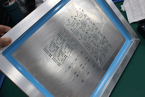
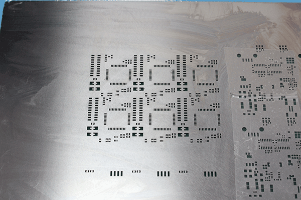
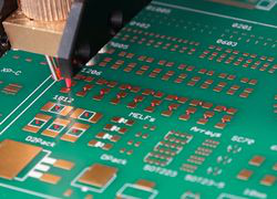
1.2 PCB Stencil
A PCB stencil is a steel sheet, with plenty of holes on it. The holes are cut by laser, to make the solder paste flow through.
1.3 Solder Paste Printing Machine
In the pasting, we need to make sure the stencil holes aim at the corresponding pads, and then we brush the scream to make sure all pads stick by screams. Of course, you can paste the scream manually, but that not works for hundreds of boards, that is why a solder paste printing machine needed.
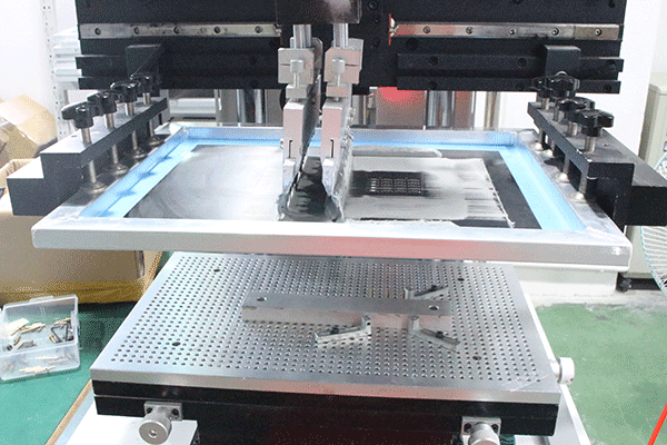
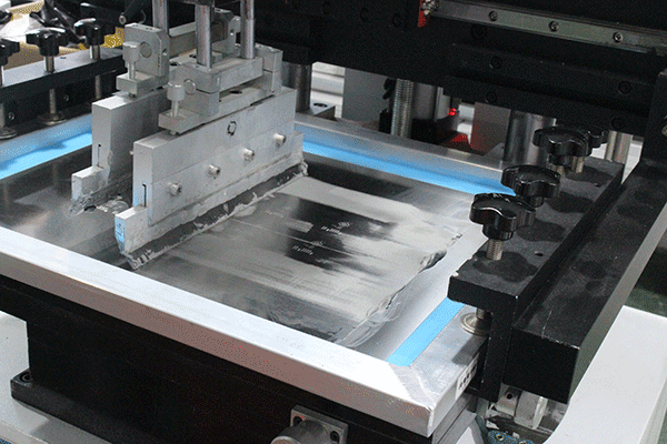
In Makerfabs, we use the fully automatic solder paste printing machine, to ensure the solder paste is brash accurate in the right place.
2: Automated Component Placement
After the PCB boards are printed with solder screams, the next step is placing the electronics components onto the bare boards.
2.1 Pick-and-Place Machine
The pick-and-place machine is the key machine in the circuit boards assembly works, which determined the quality/speed and also the max production ability. Basically, it is used to “pick the components, and place it to the right place”.
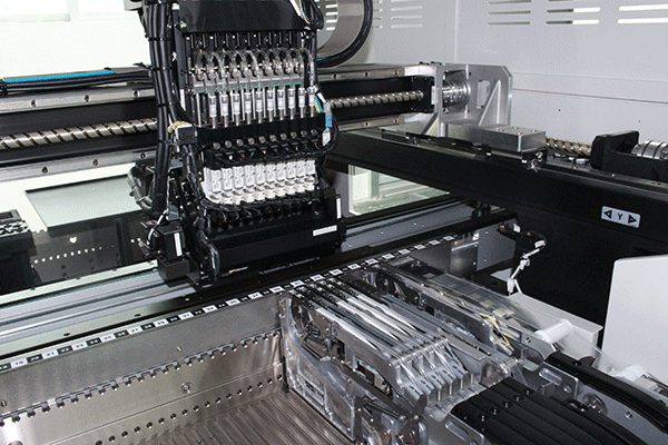
The engineers will firstly install all the needed components, such as resistors/capacitors/IC/Connectors, etc, in the special place of the machine, and then program the pick-n-place machine, to tell it “hey, put this resistor/ capacitor here”.
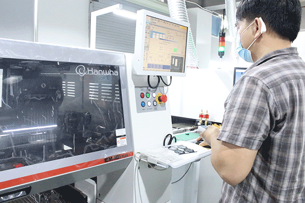
The key spec for a pick-n-place machine is how accurate it could be. In Makerfabs, all the pick-n-place we use are SM481-PIUS, which can handle resistor/capacitor 0201 packages and BGA IC with 0.3mm.
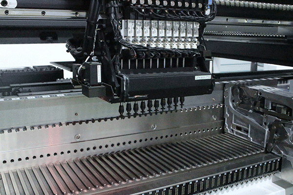
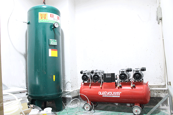
2.2 Vacuum Compressor
The pick-n-place machine work with a vacuum compressor, it draws the back of the components by a tiny nozzle, so normally, you will see dozens of nozzles in the machine.
For PCBA prototyping/ small batch assembly, the most time-cost procedure is the components installing/ programming and debugging, that is why there starting fee for a project, and the unit soldering fee drop much as the quantity goes from 10 pcs to 50 pcs.
2.3 Glue Dispensing Machine
Sometimes, there're components at PCB on both sides, that when soldering on one side, the components on the other side may drop off, especially when the components are heavy& big. The glue dispensing machine makes the glue on the PCB board, so the components will sit on the board firmly. This is important for wave soldering where the force of the solder wave may dislodge larger components, or for double-sided wave or reflow soldering to stop components from dropping off.
3: Reflow Soldering
3.1 Reflow Soldering Oven
Normally, for surface mount components, reflow soldering is used. After the components are placed onto the bare board, it will be heated by this machine called “Reflow Soldering Oven”.
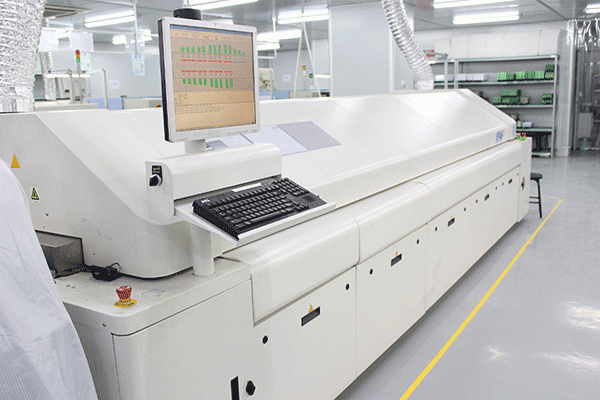
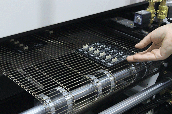
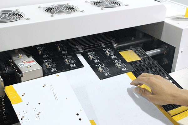
The PCBs with components placed are put into the machine from one end, On a double-track conveyor belt, the boards with newly-placed components are passed through hot and cool zones of the reflow furnace (at Makerfabs, 10 zones), to precisely control the melting and cooling of the solder to fill in the solder joints, the solder paste melts and then get solid, to form electrical connections. As the PCBA boards get to the other end, the connection gets solid.
The circuit boards are very hot as they get out of the machine, so glove needed to hand them.
3.2 Reflow Temperature Curve
The temperature curve associated with the reflow is the most important parameter to ensure the correct connection of parts. The main temperature changes associated with the reflow soldering temperature curve can be divided into four phases/zones (listed below and pictured thereafter).
- Preheating
- Constant Heating
- High-temperature Soldering
- Cooling
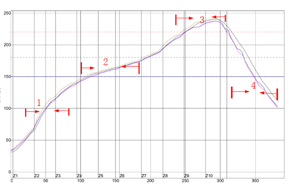
3.2.1. Preheating
The preheating zone is to volatilize the lower melting solvent in the solder paste. The preheating zone needs to volatilize the solvent but it must control the temperature rising slope.
3.2.2. Constant Heating
The setting of the constant temperature zone is mainly controlled within the parameters of the solder paste supplier and the heat capacity of the PCB. In this phase, the PCB achieves a uniform temperature, and the flux in the solder paste begins to react actively thereby increasing the wettability.
3.2.3. High-temperature Soldering
In this zone, the full melting and the wetting reaction occurs. This part of the process needs to also be carefully controlled so that the temperature rise and fall slopes do not subject the component to thermal shock. The ideal temperature and time in this zone depend is generally 220~260 degrees, 30s~60s.
3.2.4. Cooling
In the cooling process, the temperature drops, the solder scream gets solid again. It plays a key role in the final result of the weld. Too slow cooling makes components lifting, dark soldering joints, or uneven solder joints, while quick of a cool down cause thermal shock to the components.
The setting of the temperature curve is the most important for an experienced SMT engineer, there're many factors need to be considered, depends on the PCBA and component, include:
- The max temperature components can bears. For example, if there ws2812 on the boards, Makerfabs suggest not exceed 220 degrees, as our suggestions at: Why WS2812 SK6812 Failures After SMT Soldering.
- The solder cream used. Different creams may need different temperature curves.
- The components max size/max pins. For example, if they're a big power inductor, the temperature needs to be higher, to ensure the paste fully melts.
- The PCB temperature specs.
- ......
A very rough temperature is:
|
Zone
|
Lead (Sn63 Pb37)
|
Lead-free (SAC305)
|
|---|---|---|
|
Preheat
|
to 150°C in 60s
|
to150°C in 60s
|
|
Soak
|
from 150°C to 165°C in 120s
|
from 150°C to 180°C in 120s
|
|
Reflow
|
Peak temperature 225°C to 235°C, hold for 20s
|
Peak temperature 245°C to 255°C, hold for 15s
|
|
Cooling
|
-4°C/s or free-air cooling
|
-4°C/s or free-air cooling
|
4: Inspection& Testing
4.1 AOI (Automated Optical Inspection)
There after the soldering, you can’t ensure all the components are soldered OK, for many reasons such as components missing/ lifting/ cold joints… AOI is employed to detect these popular occurred problems.
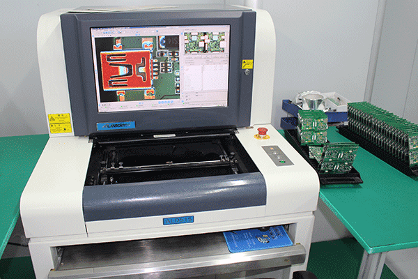
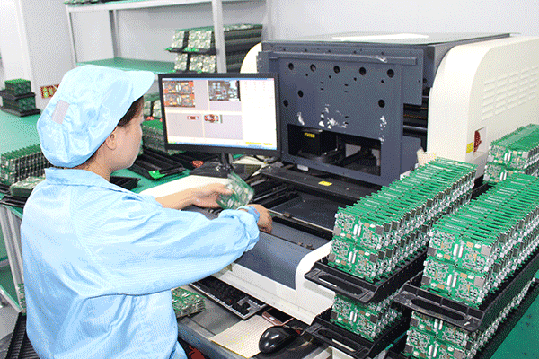
An AOI machine uses optical methods to detect defects, it uses high definition cameras to capture the surface of the board and build up an image of it for analysis. This captured image is then compared with images of a correct reference board, to identify a variety of defects include incorrect components, missing components, cold joints, etc.
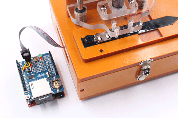
4.2 Programming Tools
For functional testing, especially for controller boards, programming tools, such as Jlink/UART tool, are needed.
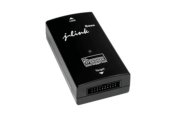
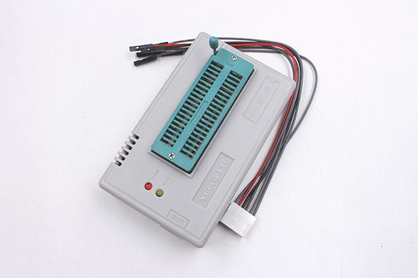
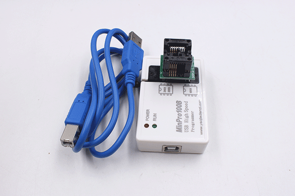
In Makerfabs, we have programming tools and related software& experience in programming for:
- PIC Chips
- Atmel Series
- ARM Series
- Arduino Bootloaders& Sketches
- FPGA
- MicroPython& Circuit Python Related
- STM Series
- ESP/ ESP32 Series
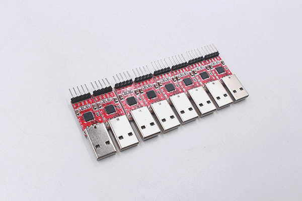
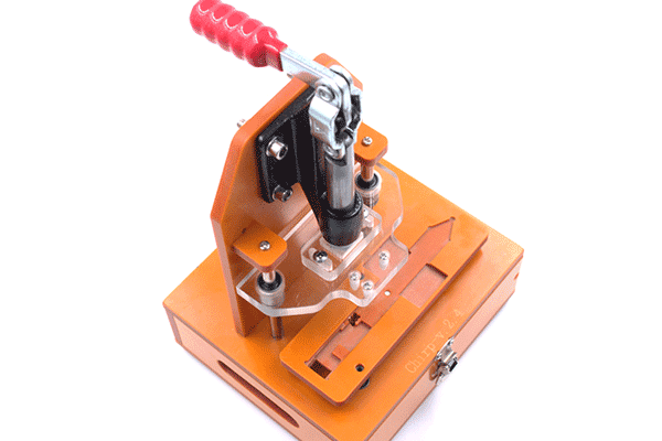
4.3 Testing Jigs
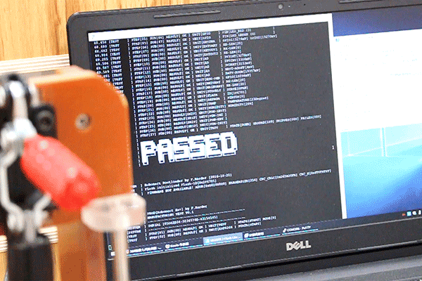
Functional testing is the key step, to ensure the final PCBA boards work as intended. Although physical defects like solder bridges or tombstones make the PCBA “should be working”, while functional testing makes the boards “ready to go”.
As a PCB assembly factory, it is hard, or even impossible to know how a customer’s boards should act. Normally it needs the PCBA designer to send the factory detailed testing steps and how to judge if the circuit boards work OK or not.
Dislike end-user usage, for PCB assembly factory, testing jigs usually be helpful to make the boards testing quicker.
A testing jig is composed of many needles, to contact the pads on the PCBA, so the tester to program and test the pads, if they work as intended. Of course, firmware/ software loaded before, to make the PCBA board works.
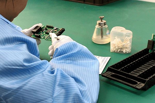
4.4 Human Visual Checking
Yes, this is the final step before the packaging. After all the machine steps, the most basic/ simple human visual checking is needed, to check if there any scars/ customer special needs, that any other problems that the machine can’t check out.
Dear Makers,
If you are finding a reliable & high-quality PCBA vendor, pls do not hesitate to contact service@makerfabs.com for your PCBA project now!
If you are finding a reliable & high-quality PCBA vendor, pls do not hesitate to contact service@makerfabs.com for your PCBA project now!